Friday, November 11, 2011

Sensors

What is a sensor? 

Sensor is a device that measure or detects a  physical property and record, indicates or otherwise respond to it. 

 Industrial sensors

    sensors are also examples of transducers.(transducer is a device that converts one physicalquantity into another quantity like voltage ..etc. ) . This sensor  technology is highly using in local Industry and in world industry .Here are some types of sensors which are highly using in industry.

Proximity Sensors 

  • mechanical 
  • Optical 
  • Inductive/ Capacitive
  • Ultra Sonic

 Position/Velocity

  •  Potentiometer
  • LVDT
  • Encoders
  • Resolvers
  • Tacho generator

Force/Pressure sensors
Vibration/acceleration
Sound sensors
pyrometers

 Proximity Sensors

 Widely use in general industrial automation.
Proximity is maiainly consist of four parts

  • Sensor head
  • Ditector circuit 
  • Amplifier 
  • Output

Catagarization of proximity sensors

 Mechanical proximity switches

                 Capable for ON/OFF operation only. Have two general modes. Very simple operation.

  • NC- normal close     
  • NO-normal open


usually used as:
  •   Limit switches
  • Presence /absence indicator 
  • Door closed / open

proximity sensors
usage of proximity sensors


Optical Proximity Sensors
(PHOTOELECTRIC/ INFRARED OPTICAL PROXIMITY SWITCH)


Optical proximity sensor is consists of mainly 3 parts
  • Transmitter 
  • Receiver
  • Amplifier relay                                         

                      A infra-red light beam is produced by emitter. This beam is sensed by receiver at another end. The emitter and the detector can be a single unit or not according to the type of the optical proximity. When this beam is interrupted by object, the receiver signal gets changed and another signal is produced.

There are three basic type of photoelectric / Optical sensors.
1-  Through beam type
               Detection occurs when the target crosses the beam between transmitter and receiver. The transmitter and the receiver are kept in different places.
Features:
  • Long-detecting distance  (up to 20m)
  • Stable detection                                                                                      
  • Opaque objects are detectable regardless of shape, colour or  material  
  • Powerful beam

Usage of this type :

  •  Conveyer /material  handling  
  •  Truck height control

 2-  Retro- reflective photoelectric sensors

                In this case both transmitter and the devise is in same component. Detection occurs when the target crosses the beam between sensor head and reflector. Receiver get the reflected beam since the system is available with a retro mirror to do the reflection.

 Features: 
  • Reflector allows for installation in a limited space       
  • Simple wiring
  • Easily-adjustable optical axis
  • Opaque objects are detectable regardless of shape, colour, or material

 Usage of this type :
  • Bottle counters

 3-  Diffuse reflective


         Diffuse sensors sense light returning from the object to be detected and switch the output when it senses.

 Features: 
  • Space-saving
  • Adjustment of optical axis not required
  • Reflective transparent objects are detectable
  • Colour differentiation possible
\

Ultrasonic Proximity Sensors
        Ultrasonic sensors operate by emitting and receiving high-frequency sound waves. The frequency is usually in the order of 200 kHz, which is too high for the human ear to hear.
 Modes of Operation
 There are two basic modes of operation,
  1. Opposed mode  
  2. Diffuse mode (echo) mode.

Opposed mode :

In opposed mode, one sensor emits the sound wave and another, mounted opposite the emitter to receive the reflected sound wave.
Diffuse mode:
   
 In diffuse mode, the same sensor emits the sound wave and then listen for the echo that bounces off an object.

Sensing range:

The sensing range is the distance within which the ultrasonic sensor will detect a target under fluctuations of temperature and also the measurements depend on the state of the medium transmitting the sound.
Blind Zone
In the blind spot, objects cannot be detected, or they even may cause error signals. The size of the blind zone depends on the frequency of the transducer. Object located within the blind spot cannot be reliably detected.
Inductive  Proximity sensors

Inductive proximity sensors are used for non-contact detection of metallic objects and they are operate under the electrical principle of inductance.

              Their operating principle is based on a coil and oscillator that creates an electromagnetic field in the close surroundings of the sensing surface.


       An inductive proximity sensor has four components;
The coil, oscillator, detection circuit and output circuit.
The oscillator generates a fluctuating magnetic field in the coil which is located in the device sensing face. When a metal object moves into the inductive proximity sensor’s field of detection, Eddy circuits build up in the metallic object and generate their own magnetic field. These fields have interaction with the coil  through mutual inductance. This cause reduce the self-field of the inductive sensor and then the detection circuit of the sensor monitors the oscillator’s strength and triggers an output from output circuitry when the oscillator becomes reduced to a sufficient level.
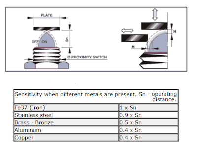
Operating Distance

  Its clear that , according to the type  of the metallic object change of oscillator’s strength may differ. But we can maintain this clearance according to the table below.         

Capacitive Proximity sensors

Capacitive sensors are primarily used when the object to be detected is non-metallic.  (both metallic and non-metallic )
The main difference between the capacitive proximity and the inductive proximity  is that capacitive proximity sensors produce an electrostatic field Instead of an electromagnetic field. 

The most common materials sensed are: plastic, glass, wood and paper. Another common application is as a liquid level controller.
Capacitive proximity switches contain 4 main components:

1-    Plate
2-   Oscillator
3-   detection circuit
4-   solid state switch
Construction of  sensing face of the Inductive proximity

                         When a   metallic object is placed near the capacitive sensor's face, the object become an another plate and forms two capacitors. This condition increases the capacitance value so that the value is  high enough to cause the sensors internal circuit to oscillate. When a Non-metallic material such as a solid or liquid is located  near the sensor head , the capacitance value increases because the object dielectric constant is greater than the air.


In above both cases ,the trigger circuit reads the oscillator’s amplitude and when it reaches a pre-set  level the output state  of the sensor changes. As the target moves away from the sensor the oscillator’s amplitude decreases, switching the sensor output back to its original state.

Friday, August 19, 2011

DDLO (Drop Down Lift On)


DDLO (drop down lift on )
DDLO is a devise that uses to protect Transformers , capacitor banmks or electrical devises from high curent surges and can consider it as a combination of fuse and a switch .
This can provide a wide range of protection for over head distribiution system rated from 10kV to 36kV .
Always DDLO conects in series with the transmition line.
For DDLO , standered voltage ratings are  maintained between
11/12 kV ,22/24 kV ,33/36 kV
Fuse cutouts are capable of carries a maximum curent of 100 A to 200 A.

Parts of the DDLO


Positioning Of The DDLO

In Sri Lnka CEB practice is to position the DDLO before the Arresrers along the high voltage circuit.(As shoen in figure A )
This concept ensure the safety of the workers who work on the
transformer during the maintainace .(As the arrester is isolated when DDLO switch is opened ) 


If the arrester can be  fixed and then the DDLO ,then there can be less DDLO failiers. (As shown in figure B )
Hence the relaibility is increased.
But this canot assure a good safety for the
workers as mentioned in above.


Technical Details


AB Switches(Air Breaker Switches)


This is commenly use for out door applications.Main function of this product is to isolate the Transformer, Overhead lines, System or Cables from distribution network.
The A.B. Switch have triple pole construction and shall be suitable for Vertical / Horizontal mounting.
This consists with a long  G.I. pipe for operation from  ground level and operating handle is specially design for smooth operation.

Special Features
  • Low Contact resistance through the life of switch.
  • Smooth and trouble free operation.
  • Sturdy design of current carrying parts.
  • Can be done the operation from the ground.

Wednesday, August 17, 2011

TRANSFORMERS


What Is A Transformer ?

Transformer is an electrical  machine that can converts electrical energy from one voltage level to another voltage level.This convertion can  be done in two ways,either steph up or steph down.
Normaly the efficiency of a  transformer is a very  high value since there is no any rotating parts in a transformer.


Classification Of Transformers
We can classified transformers in many ways .

1 - According To Insulations

    Liquid Immersed Transformers

   Transformers whose core       and  coils immersed in an insulating liquid.
Liquid should be non flammable
it can be either mineral or synthetic.

   1 - Dry Type  Transformers

Dry transformers requier less maintenace.
Negligible smoke generation.
No hazards of fire.

2 -Acording To The Number Of  Phases

Single phase transformers
Three phase transformers
three phase transformer


3 -Acording To The Purpose

Current transformers (CT)
In general ,current transformers are used to take  measurements  of electrical current.

Constant voltage transformers
Auto transformers

4 -Acording To The Construction

Core type transformers
Shell type transformers

5 -Acording to the servise

Distribiution Transformers
Power Transformers


Construction Of Transformers

There are mainly three parts in a transformer.
Primary winding - conected to the suply
Secondary winding - conected to the load
Core-core is the medium that link the primary winding flux to the secondary winding.

How does  the transformer works ?

When a AC suply is conected to the primary winding , coil will prodiuse a changing magnetic flux .This flux is directed to the secondary by the means of the core. So there will be an indiused voltage in the secondary.Out put voltage can be steph up or steph down according to the ratio of the number of turns that woun in each side.

Protection Of The Transformer

Transformers are the critical and expensive equipment of a power system.
Faliures in a transformer can be occured as ,

Winding failiers due to short circuits.(phase -phase faults,phase -ground faults,turn-turn fault,open winding)
Core faults (core insulation failiers,shorted laminations)
Terminal failiers (loose conections , short circuits)
On load tap changer failures.
high current surges ( due to lightnings . etc )

How to keep a smooth functioning of a transformer ?


For this it is essential to moniter the situation inside  of the transformer regularly.
In oil immersed transformers variation of transformers properties can identified by the monitering the oil situation inside it. To moniter this there are some equipments like Buchhoz relay ,DGPT 2
  
  Buchholz Relay
 
Buchholz Relay
Buchholz Relay is designd to detects faults as well to minimize the propagation of any damage which might occur within oil-filled transformers, capacitors and reactors supplied with oil
conservator.
Buchholz relay is located in the midle of pipe between the concervator and the transformer tank.
The devise has two elements. The upper element consists of a murcurry type switch attached to a float.The lower element containeds  a murcurry switch mounted on a hinged type flap located in the direct path of the flow of oil (coservator to the transformer).


Operation of the Buchholz relay

  1- Incase of slowly devolping faults within the transformers,some heat wil generate due to the fault.This heat decomposite the transformer oil of the main tank.The product of decomposition mainly contain of 70% of hydrogen.Hyfrogen is a very light and tries to move in to the conservator tank.On the way they are traped in the upper part of the relay chamber.When pre determined amount of  gas  gets accumilated it exerts sufficient pressure on the float to close the  murcurry switch.This completes the alarm circuit to sound an alarm.

2 -If serious fault occur in a transformer, considereble amont of gas will generated in the main tank.So the oil in the main tank rushes towards the conservator due to the pressure generated by the accumilated gas.So this cause to tilts the flap to close the contacts of mercurry switch(lover valve).This completes the trip circuit to open the circuit breaker controlling the transformer.
The relay is therefore particularly effective in case of;

  • Short circuited core laminations
  • Bad contacts
  • Over heating of the some parts of windings
  • Short circuit between phases


Furthermore the relay can prevent the development of conditions leading to a fault in the transformer,


such as the falling of the oil level owing to leaks, or the ingress of air as a result of defects in the oil circulating
system.
Disadvantages of the Buchholz relay
It can only use with the oil immersed transformers Iquiped with conservators.


Buchholz relays do not moniter the temperature
Buchholz relay only can ditect faults below the oil leveling the transformer, therefor seperate protection is need for conecting cables.

DGPT 2
DGPT 2 is also a protecting equipment which have to mount directly mounted on the tank at its highest point and with no bends. So gas bubles can traped in the devise.
DGPT 2 do all things that bucholz relay do .
And also DGPT 2 can mesure the temperature of the transformer.

DDLO

DDLO (Drop Down Lift On ) also use as a major protective equipment for the transformer.
DDLO is cnect in series with the input.


Maintaining the moisture inside of the transformer


There are three ways that moisture can come in to a transformer tank .
1 Moisture left in the transformer by Manufacture.This amount  can be 0.5 % to 3 % when the transformer leaves the factory.
2 MOisture comes through with Oil
3Through week points and during maintainus period.
Why its essential to keep moisture out from the transformer
  • Expansion of the paper insulations and making them weak.
  • Loss of insulating ability ( water break down the dielectric)
  • Increase the corrosion of the core and tank.
  • Break down the dielectric strength of the transformer oil.

Losses Of A Transformer

Sunday, August 14, 2011

ELECTRICAL TRANSMISSION LINES


High voltage curent transmission can be done  as
  •  High Voltage Direct Curent (DC)
or
  • High Voltage AC curent
But in Sri Lnka there is only High Voltage AC curent distribution system.
Beacouse AC curent distribution system consiume less cost compared with to DC curent distribution system for short distance . (below 800km)
A transmition line has three parameters

Change of AC  resistance according to the frequency

These parameters are uniformly distributed through the transmition line.
AC current resistance is greater than the DC curent resistance due to the SKIN EFFCT.
So the current density is larger near the surface of the conductor and decreasing to the center point .
Skin effect increases proportionaly with the frequency and the cross sectional area.

Construction of the transmission line

Transmition line conductors are not straight wires but strand of wire twisted together to form a single conductor to give it a higher tensile strength.

Transmition line types

Aluminium Conductor Steel Reinforced (ACSR)

  The outer strands are Aluminium,chosen for the excelent conductivity,low cost ,and low weight.The center strand is of steel for the strength required to support the weight without streching the aluminium  due to its ductility .
In the conductor there is a less current density in the middle ,since the less conductive steel bars place in the midle of the strand.

All Aluminium Conductors (AAC)
This conductor is made from aluminium-magnesium-silicon alloy of high electrical conductivity containing enough magnesium silicide to give it better mechanical properties after treatment.


AAAC (All Aluminium Alloy Conductors)
they have a better corrosion resistance and better strength to weight ratio and improved electrical conductivity than ACSR CONDUCTOR on equal diameter basis.
ACAR

INSULATORS (ELECTRICAL)

Insulators are the materials which do not allow to flow current through them.We use insulators for the protection of Users aswel as the protection of the electrical dewices.
In insulation materials, valance electrons are tightly bonded to the their atoms .So we can consider curent is not flowing through this materials.
But in the real world perfect insulators do not exsist.Thats mean any kind of insulator must have a DILECTRIC STRENGTH value.If this dilectric value is very high , we can say that material is a gud insulator.

Materials Uses For The Insulators


Insulators that are made for high tension power transmitions are made from
  •  Glass
  •  Porcelain
  •  Composite Polymers


Glass Insulators


Dilectric strength -   9.8-13.8 kV/mm.
Even glass has a higher Dilectric Strength , its Internal strains are less. So its difficult to do moulding and casting prosses.And they have a less mechanical strength.So manufactures stoped making glass insulators after 1960.


Porcelain Insulators


Dilectric strength -  4-10 kV/mm
Porcelain materials that uses to make insulators are rich of Alumina . So it gives a high michanical strength to the Isulator.


Polymer Composite Insulators


Composite Polymar insulators are less cost and lighter in the weight.
Dilectric strength of Polythylenen- 18.4-21.7kV/mm


Classification Of Insulations

Class 1 Insulations

In this concept , it is a must to ground the metal body and all ather exposed metal parts .these equipments can easily identified by the third pin on the power plug for the ground conection .

Class 2 Insulations


Also known as Double layered Insulations.This is highly used  for potable type electrical equipments.(electric shavers, hair dryers and portable power tools).  All ilectricaly energized compenents are totaly enclosed within an insulated body that privent any contact with live parts of the devise.


Types Of Insulations


Shackle Insulators

Pin Insulators


Disk Insulators

Egg shaped strain Insulators

Cap and Pin Insulators